
The Bellhousing Dial-In Procedure Is Vital
The best thing you can do to ensure the longevity of your new transmission is to make sure the engine crankshaft and input shaft are in as straight a line as possible. This is a requirement of SST’s warranty.
When the engine crankshaft and the transmission input shaft are misaligned, lateral stress is placed on the input shaft. This leads to accelerated front bearing wear, increased shifter effort (especially in 1st and 2nd gears), and an increase in transmission noise. Wear caused by misalignment is easily recognized, so to ensure you have no issues with your warranty, it is important to follow the procedure and document your results.
You must ensure that your engine crankshaft is properly aligned with the bellhousing register hole. Don’t let anyone mislead you; every new bellhousing (no matter who makes it) requires this alignment procedure. Even if you are installing a new Tremec transmission on your old bellhousing, you still must follow this procedure.
How to Dial-In Your Bellhousing – Step-by-Step
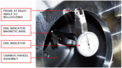
The process is fairly simple but requires a second person to assist in rotating the crankshaft while you take the measurements.
1. The first step is to assemble the flywheel to the crankshaft flange. Since we will only be using the flywheel to hold the magnetic-based dial indicator, you do not need to torque the bolts at this time. Many mechanics will only use 3 of the 6 bolts to hold the flywheel in place.
2. Once you have the flywheel secured to the crankshaft, bolt the bellhousing to the engine block. Again, make sure it is tight, but it is not necessary to torque the bolts. Place the base of the magnetic mount dial indicator on the friction contact area of the flywheel, then arrange the indicator arm so that it travels along the inside diameter of the bellhousing register hole.
3. The easiest way to measure the run-out is to rotate the crankshaft until the dial indicator is at the 12 o’clock position, and zero the gauge. Then, rotate the engine slowly in the proper direction (never rotate an engine backward) watching the gauge as the needle fluctuates. When you have found the high spot in the circle, mark it on the back of the bellhousing with a marker, and record the amount of misalignment.
This may require 2 or 3 turns to make sure you can replicate the area of misalignment. Once you have marked and recorded the measurement, rotate the crank 180° and verify the corresponding low point of the bellhousing. Mark this location and the measurement, as well.
4. After verifying the 2 points are 180 degrees apart, it’s time to get out the calculator. Subtract the lower number from the higher number then take the solution and divide it by 2. If your number is greater than .005”, you’re outside of the tolerance allowed by Tremec.
For instance, if your high point was .015” and your low point was .007” the difference would be .008” (.015-.007=.008).
When you divide .008” by 2, you get .004”. .004” is less than .005” so this example would fall within the tolerance.
If you’re within the tolerance, this is your last step!
What If My Bellhousing Is Outside of Tolerance?
So, what if your measurement comes out to be MORE than the .005" allowed? This is when offset dowel pins come into play. These pins are specially made in 3 different offsets: .007", .014" and .021" to allow for a wide range of alignment adjustments. They are sold in pairs and replace the original equipment dowel pins. Dowel pins align your bellhousing to your engine.
Installing the Dowel Pins
1. Remove the bellhousing from the motor and remove all original bellhousing dowel pins. Once you’ve removed the old dowel pins, make sure the bores are clean and smooth.
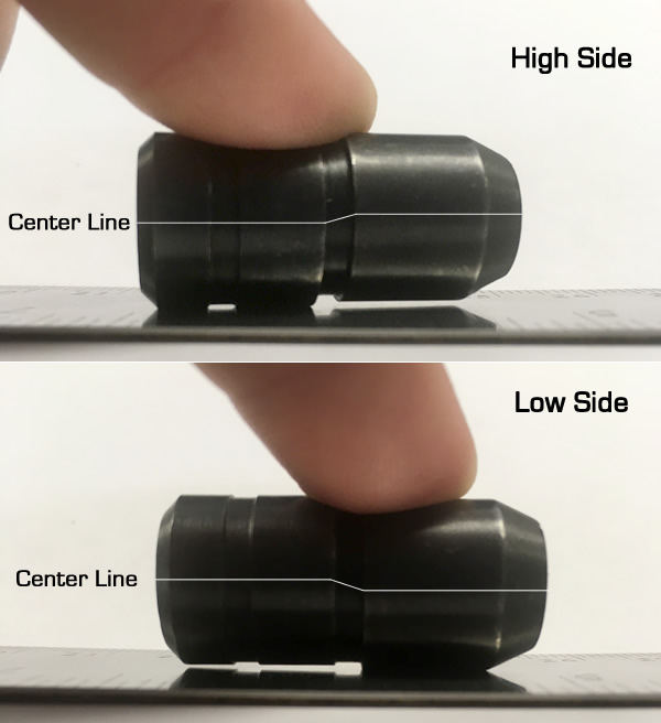
2. One side of the new dowel pin has a slot; this side goes out toward the transmission while the other side is inserted into the engine block. The dowel pin has a high side and a low side. To find the high side, place the pin on a table with the slot facing up and down. Put pressure on the pin's top and center, and one side should come completely off the table. If it’s not the slot side, turn the pin 180º, if it is, you’ve found the high side.
3. Install the dowel pin with the high side of the dowel pinpointed toward the area with the low side mark on the bellhousing. Tip: apply a little grease to the pin to make it easier to insert and rotate.
4. Install the second dowel pin parallel to the first.
5. After the new dowel pins are installed and correctly oriented, re-attach the bellhousing and set up the dial indicator again. Re-measure the alignment as you did the first time, and verify the measurements are within specification.
If not, the dowel pins may need to be rotated slightly to bring the numbers into spec. Repeat until the bellhousing meets the .005” requirement.
Once this step is complete, it does not have to be done again, unless you replace the bellhousing. As long as you use this bellhousing, you can remove and replace it over and over again, without the need to re-measure the alignment.


